How does a cycloidal drive work? tecscience
A unique principle of cycloidal gears is that the outer rolling circle used to create the addenda tooth flanks (epicycloids) on one gear is used as the inner rolling circle to create dedenda tooth flanks (hypocycloids) of the other gear. This ensures a constant angular velocity and holds up the fundamental law of gearing, which states that the.

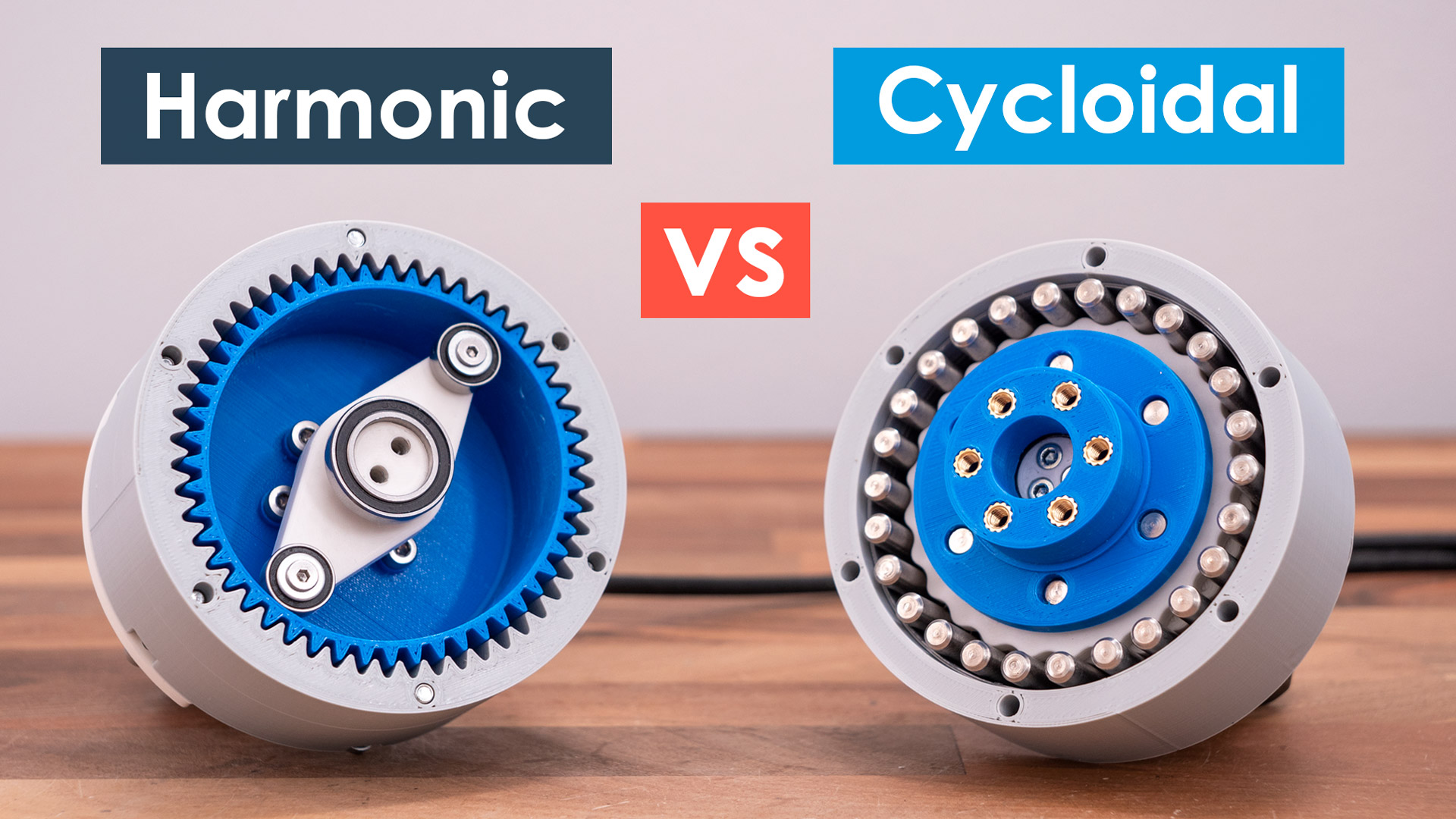
Cycloidal Gear Vs Harmonic Drive
Cycloidal drive vs. planetary gear. When it comes to large transmission ratios in a compact design, two gear types are particularly suitable: The planetary gear and the cycloidal drive. The similarities between the two gear types become particularly clear when the ring gear of the planetary gearbox is fixed. The gearbox is driven by the sun.
Solved Designing a cycloidal gear help PTC Community
A cycloid gear graphical calculator to design cycloidal drives. - GitHub - rlneumiller/CycloidalGearSolver: A cycloid gear graphical calculator to design cycloidal.
How does a cycloidal drive work? tecscience
Cycloidal Gear Calculator British Standard 978, Part 2. Module: mm Number of wheel teeth: Number of pinion teeth: Circular pitch: mm Dedendum: mm Gear ratio: Addendum factor: Addendum:. Dr. Rainer Hessmer's Cycloidal Gear Builder.
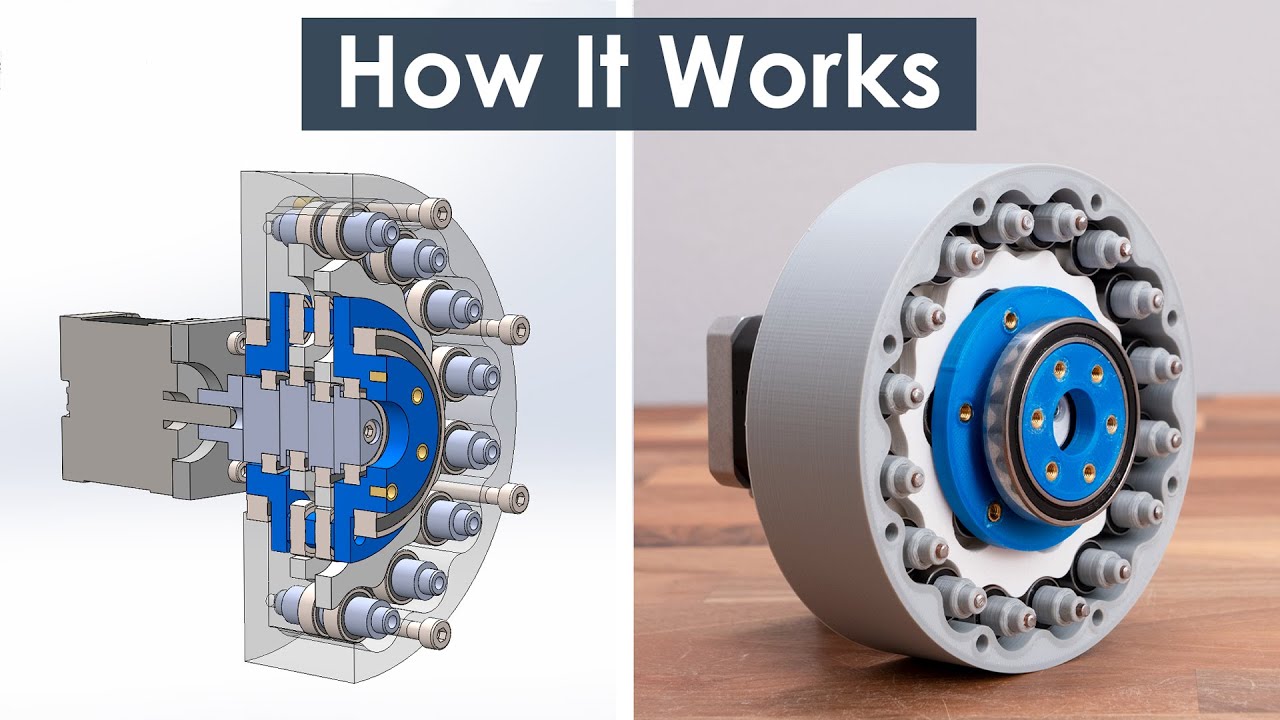
What is Cycloidal Drive? Designing, 3D Printing and Testing YouTube
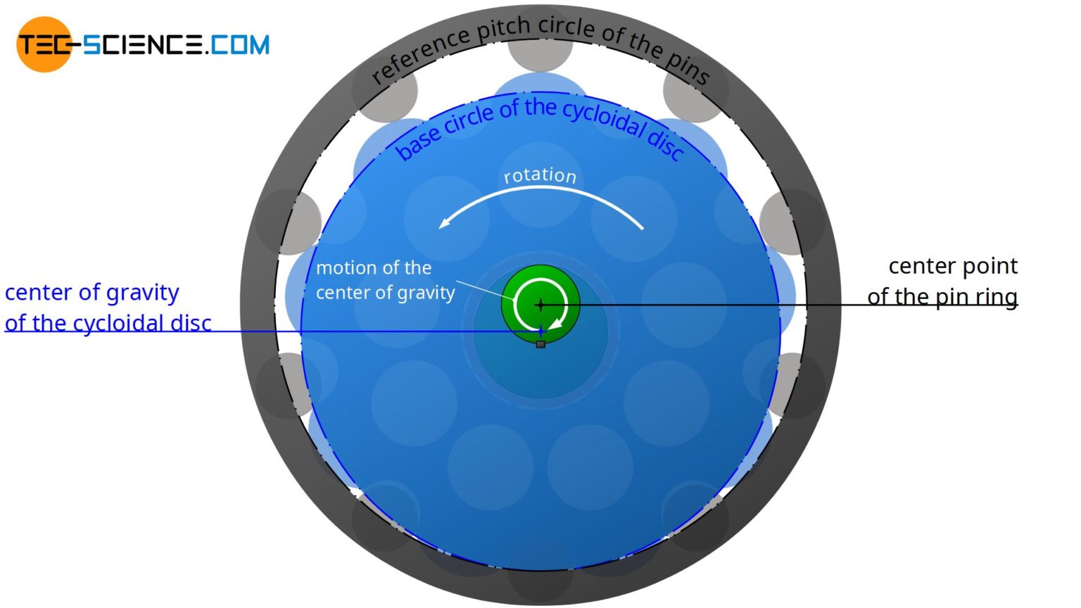
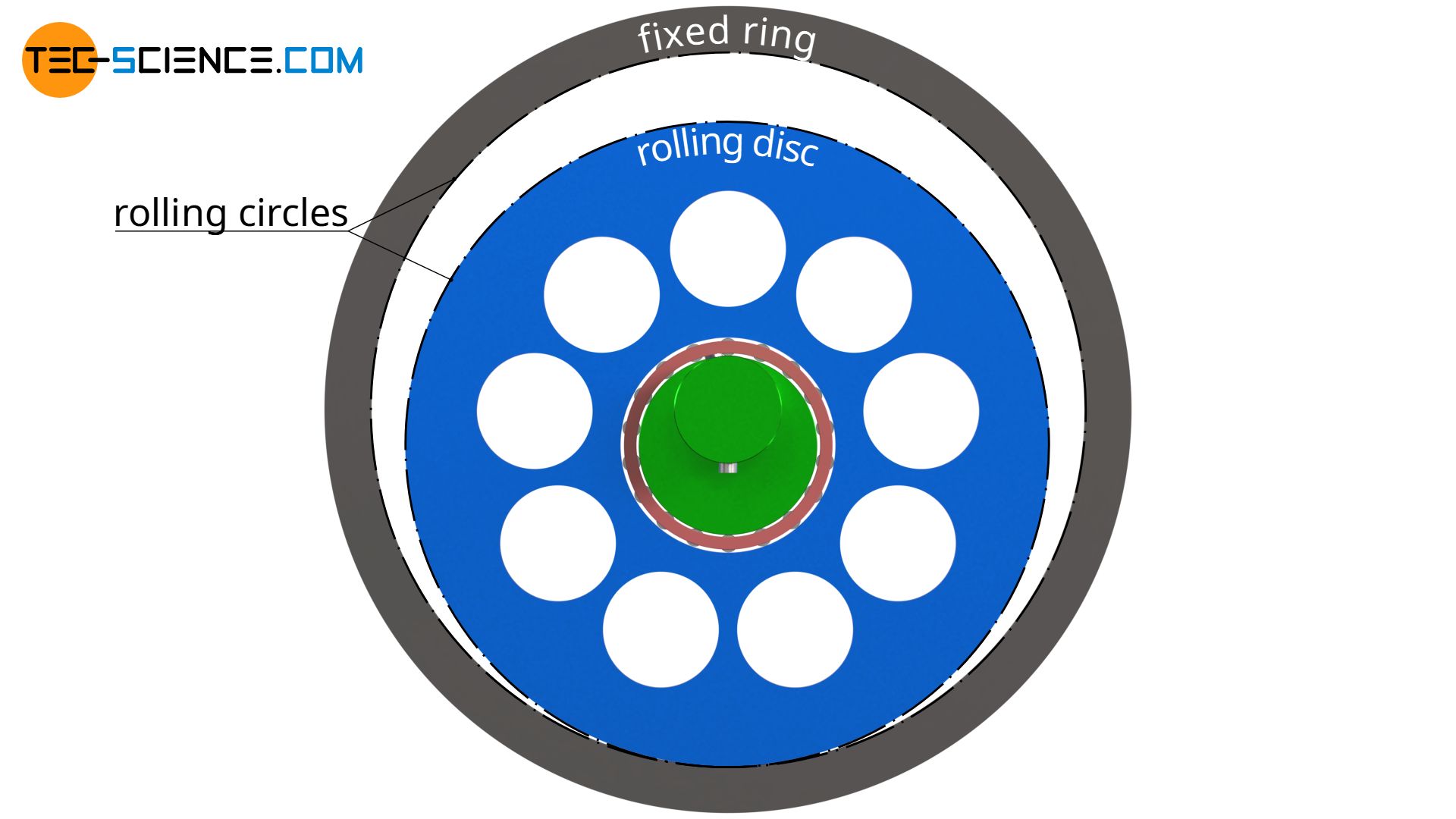
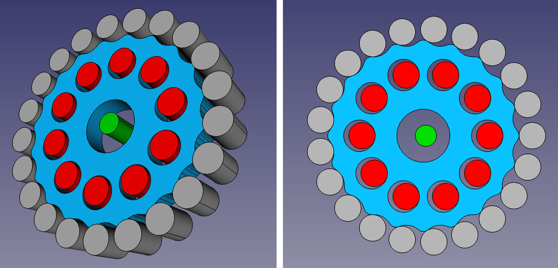
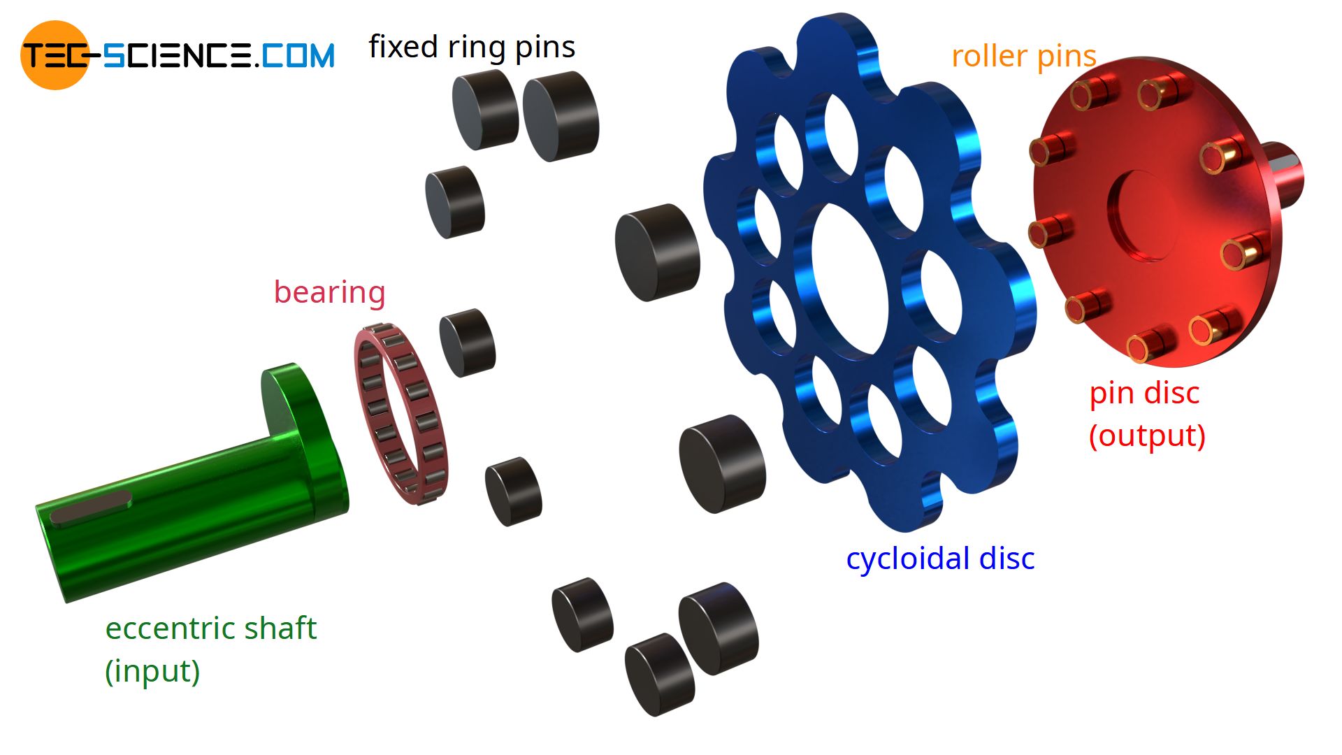
Cycloidal drive. A cycloidal drive or cycloidal speed reducer is a mechanism for reducing the speed of an input shaft by a certain ratio. Cycloidal speed reducers are capable of relatively high ratios in compact sizes with very low backlash. [1] The input shaft drives an eccentric bearing that in turn drives the cycloidal disc in an eccentric.
3D Printed Cycloidal Gearboxes RepRap Ltd
Step 1: Find the Motor RPM. If you're wondering how to find gear ratio for our Cyclo, you'll need the motor RPM. To calculate this gear ratio, let's use a Cyclo 6000 that has 1800 RPM at the VFD. Step 2: Find the Final Output RPM. The next most important piece of the gear ratio equation is the final output RPM of the industrial gearbox, as.

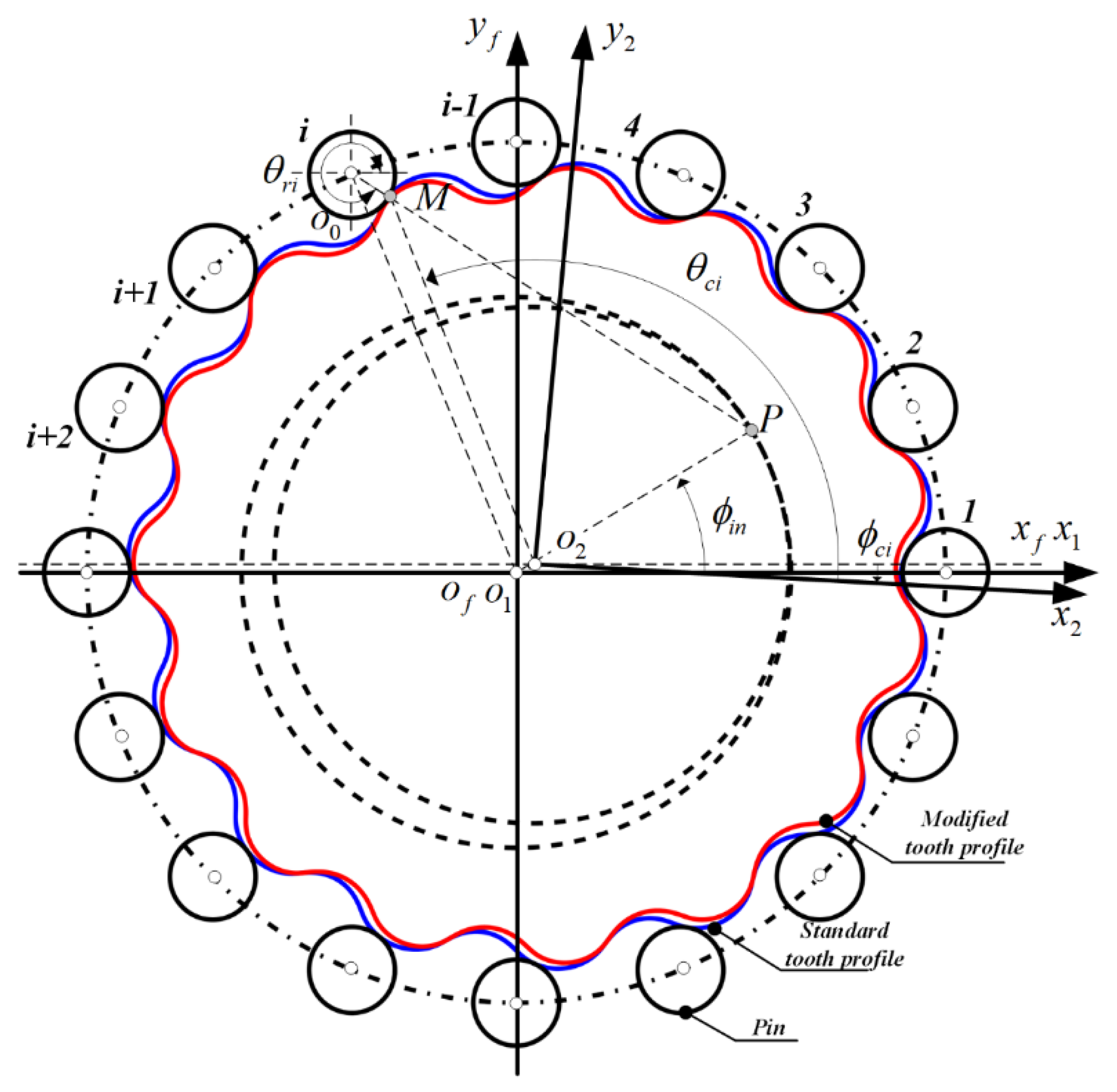
Tooth profiles (A0, A1, and A2) of the theoretical cycloidal gear a0... Download Scientific
Friction: Involute gears normally mesh with 2 or 3 teeth in contact at the same time while cycloidal gears can be designed so that only 1 or 2 teeth are in contact at a time. Because some sliding contact occurs in all gear designs, involute gearing will tend to have more friction that a comparable cycloidal design.

Dr Rainer Hessmer
How to Design an Eccentrically Cycloidal (EC) Drive. How to Design and Test the Automotive Differential in Blender.. Involute Gear Calculator. The following online calculator computes the basic dimensions and tooth profile of an involute gear based on its module, number of teeth and pressure angle (the latter is usually 20°)..
How does a cycloidal drive work? tecscience
Cycloid gear online calculator. The tooth profile is a general term for cylindrical gears of various cycloidal lines or their equidistant curves. Cycloidal gears have few teeth and are commonly used in instrumentation and are less used as power transmissions. Its derivative type cycloidal pin wheel drive is used more.
Harmonic vs Cycloidal Drive Torque, Backlash and Wear Test
A cycloidal gear can be drawn as an alternating sequence of hypocycloid and epicycloid arcs. This Demonstration shows the generating circles rolling along the pitch circle while generating the gear profile. Contributed by: Erik Mahieu (March 2013) Open content licensed under CC BY-NC-SA.

How do cycloidal gears work and where are they used?
Online Cycloidal Gear Builder. Almost exactly a year ago I published a blog post introducing an open source application for calculating cycloidal gears. The response was very positive but the fact that the tool depends on a specific version of .Net makes access a bit cumbersome. Also the tool does not immediately show the resulting gears.
Applied Sciences Free FullText A SemiAnalytical Load Distribution Model for Cycloid Drives
The calculations reflect the British Standard 978, Part 2. They are based on Hugh Sparks' excellent write-up on cycloidal gears and his associated JavaScript based calculator. Instructions. Specify desired values in the parameters box and then click on the 'Update' button. Dependent on the specified resolution the rendering might take some time.
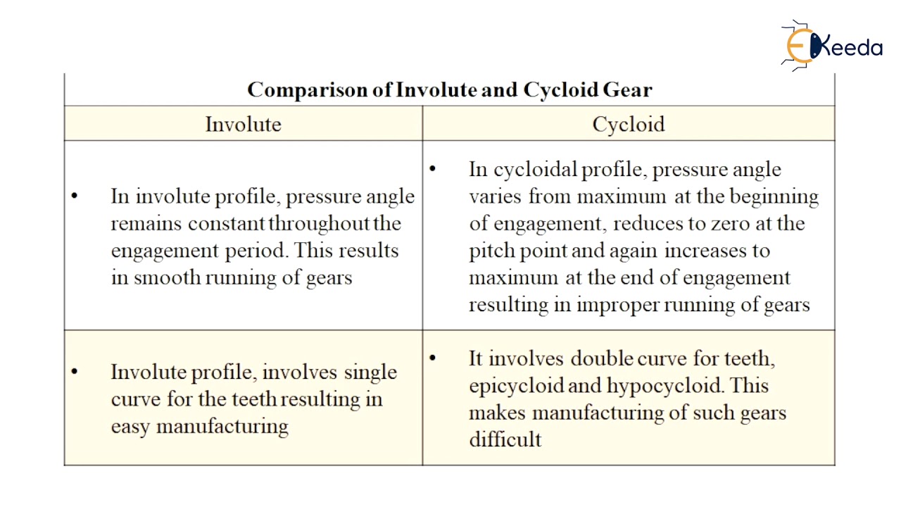
Comparison of Involute and Cycloidal Gear Design of Spur, Helical, Bevel and Worm gear and Gear
Create excel file, Create new drawing, add parameters, create sketch, draw equation, extrude cycloidal gears. Modify Parameters in excel, save, update in Inv.
Difference Between Involute And Cycloid Gears? Mechanical Education
The compound reduction cycloidal gear train handles all ratios within the same package size, so higher-ratio cycloidal gear boxes become even shorter than planetary versions with the same ratios.

Mechanical notes Machine Drives ( Gear Drives ) (13) ( Comparision between involute and
e - Eccentricity, or the shift of the cycloid disk's center relative to the center of the pin ring. The parametric equations generated by this calculator define an epitrochoid curve from which the actual profile of the cycloid disk (shown in red) is easily obtained using Blender's Inset tool. The inset amount equals the pin radius (d / 2).
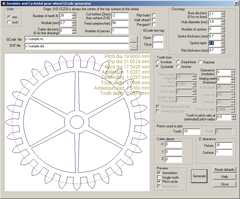
Involute and cycloidal gear designer GCode Generator
Cycloid gear graphic calculator. This is a little utility to help in the design of cycloidal drives. It is a port to C# of this python script. with some added features (mainly, the graphical display). This is some quick code I put together one day, but is contains a nice design that allows for easy visualization of any complex formula, so it is.
